Motion in a straight line
October 27th, 2009 at 10:45 pm (Books, Engineering, Technology)
It’s easy to get something to move in a circle; just pin one end down and rotate the rest (like the kind of compass you draw with) or pin the center down and rotate (like a merry-go-round). But how do you get something to move in a perfectly straight line, as is needed, for example, in engines with pistons? I’m reading a delightful book from the 1960’s called “The How and Why of Mechanical Movements,” and the subject of straight-line motion came up in chapter 2 (Levers).
It turns out that a clever arrangement of a collection of rigid bars, connected into a linkage, can give you this magical straight-line motion. Various inspired inventors have come up with different ways to achieve it, and their concepts are illuminating and fascinating.
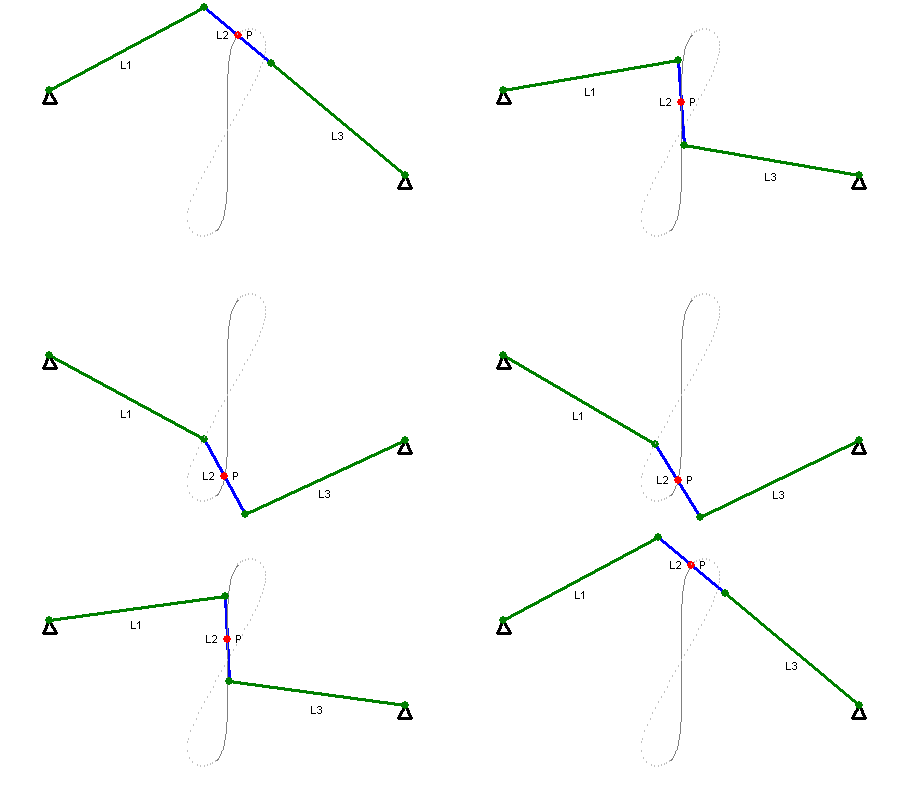
 There’s Watt’s linkage, which requires only three links. It doesn’t quite produce perfectly straight motion (note path of the red point in the animation at right), but good enough that it was used by early steam engines. It’s still used in the rear axle suspension of some vehicles, so that no sideways motion is permitted between the body of the car and the axle (the axle only moves in a vertical straight line with respect to the car body).
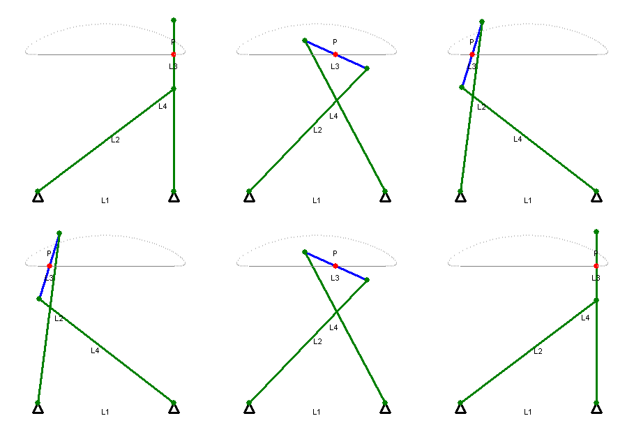
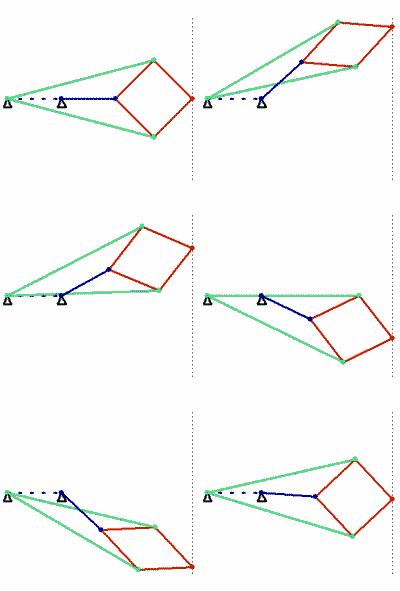
The Chebyshev linkage (below left) likewise uses three links and achieves a straighter line, within a prescribed range. In 1864, the Peaucellier-Lipkin linkage (below right) was invented, and it even comes with a proof of collinearity. (These animations are awesome!)


The authors of “How Round is Your Circle?” (another book that looks absolutely engrossing) have an excellent supplementary website. One page shows some beautiful physical incarnations of the almost-straight-line linkages as well as the truly straight-line linkages (check out the videos!).
And now, I’m off to read about more fabulous mechanical movements and be awed by others’ ingenuity.
Evan Dorn said,
October 28, 2009 at 2:16 pm
This is pretty cool! I hadn’t seen these linkages before.
Of course, you can convert any imperfect linkage into a perfectly straight line by having one component follow a guide, like a slider on a rail or a piston in a cylinder, and introducing a degree of freedom somewhere else; one of the pivots follows a slot in an arm rather than being fixed to a single point.
One I recently learned about that really impressed me uses a slot and a Reuleaux triangle to convert rotational motion into not just linear motion, but nearly square-wave linear motion instead of the sinusoidal oscillation that pistons produce: http://www.youtube.com/watch?v=9Bt_wLqjPeI
By the way, I’d love to borrow that book when you’re finished with it.
Terran said,
October 29, 2009 at 1:18 pm
Nifty! Yeah, there’s this whole world of physical objects that I know next to nothing about. It’s neat to see under the hood sometimes!
So a natural, and somewhat computational-feeling, followup question is:
Given an arbitrary simple open curve in the plane (or, more generally, d-Euclidean space, for d>=2), is it possible to arrange a finite collection of rigid rods, fixed to each other or to the reference frame only with rotational joints, such that a fixed point in the linkage traces out the desired path? If so, (a) is there a constructive proof (i.e., an algorithm) for a given curve and (b) what is the minimum set of such rods required for a given curve?