Digital Dominoes

As part of Kids Building Things, we’re hoping to offer kids a basic electronics workshop. Our current plan is to show them how to make Digital Dominoes, which are about the size of an analog domino but, instead of physically toppling, they propagate using LEDs. The first step was for me to give the project a test-run to see how difficult it is and how long it might take.

At right you can see the parts (click to enlarge) that come in a kit of four ($20). (If you look closely, you’ll note that my kit is missing one red LED, so I’ll need to swap in from my own supplies to make all four.)

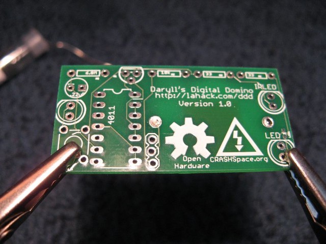
I carefully inventoried the kit and read through the assembly instructions. Then it was time to plug in the soldering iron and get started! Below you can see the empty board.

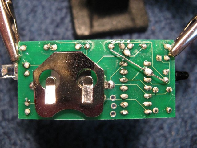
Below is the back of the board, after I soldered all 40 joints. The first tricky bit for me was the NPN transistor, whose three joints (the triangle cluster at top) were so close together that I accidentally soldered all three together. This was quickly solved with the solder sucker and re-soldering them separately. The other tricky bit was that due to a “bug” in the board, you have to patch in a connection between two pins from separate components by bending the soldered leg of one onto pin 2 of the IC. Soldering the leg to the already-soldered pin seemed to suck the solder up out of that joint, and I worried that I’d lost the connection. I used my multimeter to check connectivity, and happily all was well. I trimmed the extra leg bit after this image was taken.

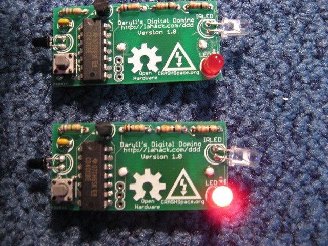
And below is the final product! (I manually triggered one for the photo — they don’t actually interact in this configuration.) The black photoresistor at left receives light, turns on the red LED, and also activates the clear IR LED at right, sending out a signal for the next digital domino in a chain.

It took me 70 minutes to make the first one, going carefully, and only 25 minutes to make the second one. Excellent soldering practice! I can’t wait to make some more and play with them — and then teach kids how to make their own!

Replacing my car stereo

I finally got sick of the cassette adapter I was using so that I could listen to my iPod Shuffle in my car and decided to upgrade my car stereo. It turns out that you can get a new base model for $60-70, which was much cheaper than I’d thought! (It really doesn’t take much to leapfrog the technology used in my car’s original 1999 stereo.) Then it’s just down to the investment of your own time to get it installed. (Given Evan’s offer to show me how it’s done, there was no way I was going to pay an installer to have all that fun!)

There were several new features that I wanted: a front AUX input, so I could plug my Shuffle in directly; a display that showed the title of the song currently playing from the radio; and a CD player. At Best Buy, the front AUX port and the CD drive were easy to spot on any stereo, but I couldn’t tell which ones would show song names. I asked the salesperson, who replied, “All of them.”

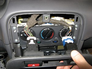
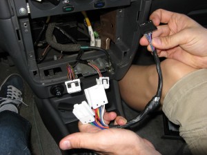
I picked out the base Pioneer model (1300MP), and a few days later we got together to install it. Evan figured out via google the easiest way to open up my console, and after detaching the wiring plugs for the hazard and rear defrost buttons, we had the stereo out:
We opened the new stereo and commenced to connect its wires to a “wiring harness” that has plugs to fit the sockets provided by my 1999 Nissan Sentra. This meant stripping the ends of 11 wires and then soldering them to their corresponding wires in the harness. I experimented with my “less hazardous” lead-free silver solder, but ended up switching to Evan’s “wash hands before eating or smoking” lead solder, which works tons better. Prior to soldering, Evan threaded bits of heat-shrink tubes onto each wire, and after they were connected, we slid the heat-shrink up over the join and melted it with a device like a super-super-charged hair dryer. The tubes shrank to a neat fit onto the wires, yielding tidy connections that wouldn’t short against each other (stereo out of view on the left, wiring harness on the right):
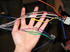
We then wrapped electrical tape in spirals along the length of the wires to package them up prior to putting the stereo back into the car.
And with that, it was in! It took us about an hour and 15 minutes from start to finish.

I enjoyed the stereo for about 10 minutes until I realized that while the CD player and the AUX port worked fine, it didn’t display anything about the current song playing from the tuner. Arrrrgh! I pored through the manual and found no mention of this feature at all. So I went back to Best Buy where the installer tech informed me that this feature is called Radio Data System and that I needed to find a stereo with “RDS” listed as a feature. He assured me however that Best Buy would take the stereo back since I’d bought it thinking it had a feature it didn’t, even though I’d already installed it.

On Amazon, I found a base-model Sony car stereo (350MP) that does have RDS, and is slightly nicer all around than the Pioneer, for only $10 more. When that one arrived in the mail, I sat down, this time solo, to undo and redo the installation process. Getting the heat-shrink tubes off the wiring harness was a pain:
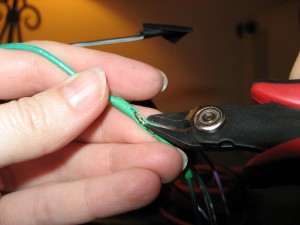
After a few of these I figured out that I could instead score the tube in the middle and twist/slide it away from the join, then desolder the connection and pull both tubes off. Then even that got tedious, so I started just cutting the wires and stripping them back a bit more to expose fresh surfaces on the wiring harness end. I put on new heat-shrink tubes, then soldered the new stereo to the harness wires and used my multimeter to check that all of the connections were good. I shrank the heat tubes, wrapped the connection in electrical tape, and put the stereo into the car. Interestingly, it wouldn’t power on until I also plugged in the antenna cable — leading me at first to suspect a flaw in my work. But no! All was good with everything connected.

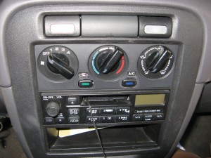
It was at about this point that I realized I’d left a CD in the stereo I’d just taken out of the car. At that point I was two hours in and not willing to remove the new Sony stereo, unsolder its connections, reconnect the Pioneer, eject the CD, undo its connections, and reconnect the Sony. So I called it a day and savored the Sony’s futuristic blue glow, dancing equalizer dots, advanced display, and Radio Data System.

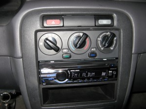
Old stereo… new stereo!
Epilogue:

  • To avoid the hassle of soldering, apparently it is possible to use wire nuts (though they may not last as long) or a kind of wire-crimping device that is what Best Buy installers would use.
  • When I took the Pioneer stereo back to Best Buy, they sadly were not willing to take the time to get my CD out of it (e.g., pull out the Pioneer display stereo, plug the one I had in, and eject the CD). So I ended up returning it with the CD inside. At that point, any route to recover the CD would cost far more (in money and/or time) than simply replacing it. I did try hooking up the yellow (+) and black (-) wires to a 12V power supply, but that had no effect, and I didn’t want to experiment further and kill the stereo in the process.
Why audio connectors are called “jacks”

Make: Electronics by Charles Platt is one of my current favorite books. I’m working my way through it, experiment by experiment, and learning tons about circuits, components, soldering, schematics, and more along the way. Recently I was working with switches and relays and learned an interesting bit of etymology.

Switchboard operatorsSwitches permit the controlled connection, or disconnection, of a circuit. We’re all familiar with light switches, doorbells, computer on/off switches, etc. Less familiar (now) is the telephone switchboard, for which an operator had to be able to selectively connect together pairs of the thousands of possibilities, as quickly as possible.

Charles E. Scribner, a man of great ingenuity, developed the “jack-knife switch” to make fast switching possible. This was a plug with a jackknife-like handle (hence the name) that could be inserted into a socket to activate the switch. Two such plugs at either ends of a cord allowed the connection of any two sockets, yielding an active telephone connection.

Although switchboards are no longer used today, the same jack-knife switch design was used to design audio connectors — which is why we refer to those plugs as “jacks”, even though no knife handle remains. I had never thought to wonder why they were called that!

I fixed my touch-lamp!

I’m delighted to report that my first soldering project is a brilliant (lit.) success. After picking up a soldering station and a coil of silver solder from Fry’s yesterday, I was all set to make my attempt at replacing the bad triac that rendered my touch-lamp useless. I’d previously desoldered the bad triac and removed it, so all I needed to do tonight was solder the new one in.

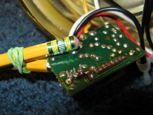
Or rather, all I needed to do was solder it in, correctly the first time. Fry’s was woefully lacking in desoldering equipment so I had no way to properly undo and cleanup any mistakes I might make. Also, Fry’s didn’t have any helping hands, so I had to find a creative way to hold the circuit board fixed while I wielded the soldering iron in one hand and the solder in the other. It turns out that two pencils, a rubber band, and a weight were sufficient.

Here is the circuit board before I began soldering:


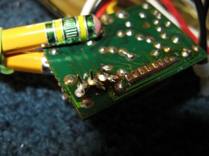
And here is the result:

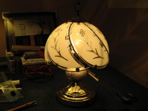
Critique: To my completely inexperienced eyes, I think I might have used a bit too much solder. It was a little tricky to get my soldering iron’s “screwdriver” tip positioned to heat precisely one of those posts at a time; a smaller tip would have been easier, I think. Also, by all reports a good solder job should leave you with very shiny clean connections — but these dulled when they cooled so I’m not sure if there were impurities or I didn’t keep it hot enough or some other issue. So it was with great apprehension that I plugged the lamp in, but voila!


You can’t tell from this static image, but it DOES work, flipping between off-low-medium-high brightness when you touch any metal part of the lamp. Yowza!

Here’s the other side of the circuit board, with the new triac clearly visible (and correctly oriented, or the lamp wouldn’t have worked):

I know that you generally clip the wire ends of components after soldering them in, but the triac’s ends were pretty thick so I just left them there. To anyone with more experience, would you clip these as you would resistor wires?

Replacement triac: $1.19
Soldering station: $39.99
Silver solder package: $3.99
Sweet, sweet success at something I’ve never done before: Priceless

Desoldering a bad triac

Some time ago, I wrote about the demise of my touch-lamp. After the bulb burnt out, the lamp no longer responded to touch. A bit of research online suggested that the triac had likely been destroyed by the bulb’s dying throes. It looked like this could be solved by replacing that part, but I wasn’t quite up to tackling it on my own.

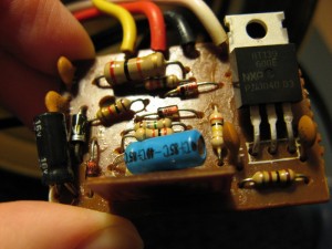
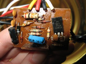
Times have changed! I read through some excellent repair instructions (thanks to a helpful commenter on my original post) which noted that most such lamps are equipped with a BT134 or BT136 triac, which can only handle up to 4 amps of current. Simply replacing this component with a BT139 triac should solve the problem forever — BT139s can handle up to 16 amps. Thus encouraged, I pulled the base off my lamp and found, to my delight, that the author of those instructions was spot-on: my lamp had a BT134! Here’s the whole circuit board, with the three-pronged triac on the right:

The letters on the triac say “PH 500E BT134 m9650”. I’ve located the equivalent BT139 part which costs all of $1.19. (What’s sad is that the BT134 costs $0.87, so for just 32 cents more, the manufacturer could have saved me this hassle. But most manufacturers probably don’t want to spend 32 cents more to build the lamp even if I am willing to pay 32 cents (or even a dollar!) for a higher-reliability product, since they’re doing mass production and mass advertising and trying to beat their competitors’ prices, etc.)

The next step is to remove the old part and replace it with the new one. My boyfriend Evan seized on this opportunity to teach me how to solder. He demonstrated soldering two wires together, and I eagerly observed and then got to try it myself. Unlike stained-glass soldering (my only previous such experience), you don’t use flux to prep the surfaces you’re joining, but instead the solder has a “rosin” core that performs the same function. The solder container had a warning on it that included “do not breathe the solder fumes, and wash hands before eating or smoking”, which cracked me up. You heat the soldering iron above 370 F (the melting point of solder), wipe the tip of the iron on a sponge to clean it, then “tin” the tip with a dab of solder. You use the iron to heat the wires to be soldered, so that they are hot enough to melt the solder as well (rather than touching the iron to the solder directly, which would be harder to direct where you want it). On touching the tip of the (solid) solder to the hot wires, it melts and flows into crevices and gaps to seal the wires together.

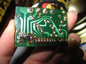
After joining the two wires, Evan showed me how to desolder, both with a copper wick (an absorbent braided fabric that sucks up liquid solder) and with an aspirator (that suctions the liquid solder away). Encouraged by this example, I desoldered the bad triac out of the circuit board. Here’s the result (this is the back side of the board shown above; the desoldering took place on the left side near the scorch mark):

Now I just need to wait for the new triac to arrive, then borrow a soldering iron and stick it back in. (Or maybe I’ll have my own soldering iron by then!) And then, victory over the broken lamp will be mine!

Update (Feb. 13, 2011): I have successfully fixed the lamp!